Our scientific projects
Decades of focus on biomechanics and human movements have led Arsalis to actively contribute to various national and international research projects covering aerospace, clinical research and other scientific domains. Each project reflects our rigor to scientific precision, positioning Arsalis as a trusted partner in the advancement of technology and scientific exploration.
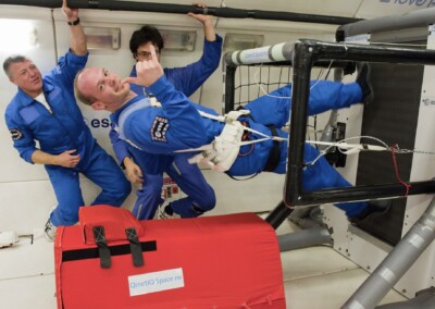
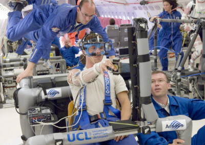
GRIP
GRIP explores the motor control of the precision grip when manipulating objects with the fingertips.
See project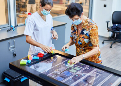
FRITE@Home
FRITE@home brings intensive bimanual therapy including the lower extremities into the home of patients with cerebral lesions.
See project